Auxiliary port synchronization signalling
The auxiliary port offers a synchronization interface for applications where it's critical that the time delay between the
synchronization input and the transmission is at a minimum. The downside is that you can only synchronize the WBT that you are connected with.
Synchronization output
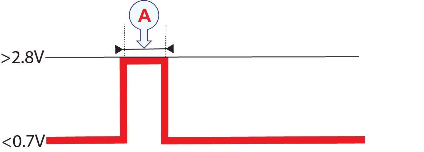
When transmit synchronization on the Auxiliary socket is enabled, the transmission is delayed until a trigger pulse is detected on the input.The input trigger pulse must be a low-to-high transition. "Low" level must be less that 0.7 V, while "High" must be above
2.8 V. "High" level must not exceed 15 V!Once the trigger pulse is detected, the WBT will initiate transmission.
| A | Trigger interval The trigger interval must be minimum 1 ms.
|
The WBT must have completed a full receive period, before being able to start the next transmission. If the WBT is not ready, the input signal will be ignored.
Synchronization output
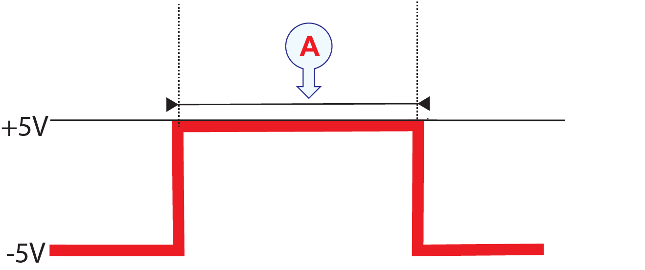
The synchronization output on the Auxiliary socket offers a "high" pulse (5 V, 100Ω) that stays "high" during the entire "ping" sequence.The pulse is always there no matter which synchronization settings you make in the user interface.The output can be used to synchronize other hydrographic systems with the EK80 system as "master".
| A | Transmit/receive period |
When the WBT has completed a receive period and is in armed state the, output is a “low” pulse (-5 V, 100Ω). The signal must be “low” before a new transmission can be detected.
Synchronization Tx status
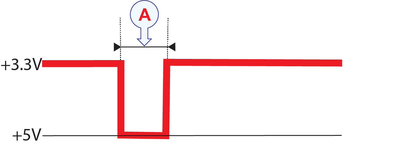
The Synchronization Tx Status signal on the auxiliary socket offers a “Low” signal (0 V) when the wideband transceiver is transmitting. The signal interface is an open-collector output and is pulled “high” (+3.3 V) within 1 ms after the transmission pulse has
been completed. The output can be used to notify other systems that the WBT is transmitting.
| A | Transmission active period |
If the user interface for the Synchronization Tx Status requires a higher signal level, the output can be pulled up to the
required voltage via a pull-up resistor. The resistor value must be selected to maximum sink 200 mA.
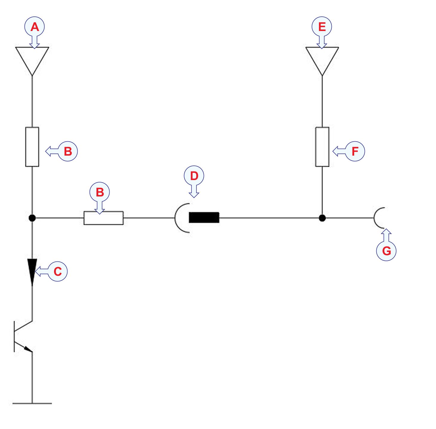
| A | Power supply: +3.3 V |
| B | Resistor: 100kΩ |
| C | The current must not exceed 200 mA. |
| D | Synchronization Tx status Pin |
| E | +Vs |
| F | Resistor: The current must not exceed 200 mA. |
| G | User Interface |