Prerequisites
The EC150-3C is installed according to the relevant installation instructions, and connected to the EK80 Processor Unit with a high capacity Ethernet cable. All units are turned on.
Context
The ADCP transceiver installation parameters are defined using the Transducer Installation page. The Transducer Installation page is located in the Installation dialog box.
Procedure
|
2 |
On the Setup menu, select Installation.
Observe that the Installation dialog box opens. This dialog box contains a number of pages selected from the menu on the left side.
|
|
3 |
On the left side of the Installation dialog box, select Transducer Installation. |
|
4 |
If relevant for your transducer installation, provide the accurate physical location of the transducer with reference to the
vessel’s coordinate system.
Use the centre of the transducer face as reference, and define the offset values related to the Ship Origin.
If available, the rotation angle used at the time of installation should be compensated for in all the offset values.
|
a |
Use the dimensional survey report to find relevant rotation angle information. |
|
b |
Insert the values.
|
• |
Specify an angle (in degrees) to compensate for any deviation from the X axis (fore-and-aft direction) in the vessel coordinate
system. |
|
• |
Specify an angle (in degrees) to compensate for any deviation from the Y axis (athwartship direction) in the vessel coordinate
system. |
|
• |
Specify an angle (in degrees) to compensate for any deviation from the Z axis (vertical direction) in the vessel coordinate
system. |
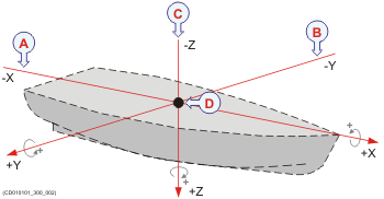
Keep in mind that in its default position (all axis set to 0 (zero)) the transducer points straight down with the orientation
mark (arrow) pointing forward. This default position must always be used as reference for rotation adjustments. To set the angles correctly, observe this exercise.
|
|
a |
On the Installed Transducers list, select the transducer. |
|
b |
Select Edit to change the settings. |
|
c |
Select the offset value on the X axis (fore-and-aft direction) from the Ship Origin. Adjust with a positive value for X if the sensor is located ahead of the ship origin. |
|
d |
Select the offset value on the Y axis (athwartship) from the Ship Origin. Adjust with a positive value for Y if the sensor is located on the starboard side of the ship origin. |
|
e |
Select the offset value on the Z axis (vertical) from the Ship Origin. Adjust with a positive value for Z if the sensor is located under the ship origin. |
|
f |
Select Save to save your choices. |
|
|
5 |
Continue your work in the Installation dialog box, or select OK to close it. |