Vessel coordinate system
The vessel coordinate system is established to define the relative physical locations of system units and sensors.
When you have several different sensors and transducers on your vessel, and you wish each of them to provide accurate data,
you need to know their relative physical positions. The antenna of a position sensor is typically mounted high above the superstructure, while a motion sensor is located close
to the vessel’s centre of gravity. Both of these are physically positioned far away from the transducer, which may be located
closer to the bow. Very often, the information from one sensor depends on data from an other. It is then important that the relevant measurements
are compensated for these relative distances.
Example
If you wish to measure the actual water depth, you will need to know the vertical distance from the echo sounder transducer
to the water line. Since the vessel’s displacement changes with the amount of cargo, fuel etc, the physical location of the
water line on the hull must either be measured at a regular basis, or measured with a second sensor.
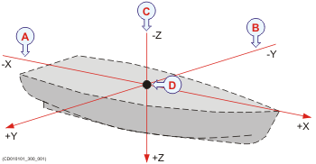
In order to establish a system to measure the relative distance between sensors, a virtual coordinate system is established.
This coordinate system uses three vectors; X, Y and Z.
| A | The X-axis is the longitudinal direction of the vessel, and in parallel with the deck. A positive value for X means that a sensor or a reference point is located ahead of the reference point (origin). |
| B | The Y-axis is the transverse direction of the vessel, and in parallel with the deck. A positive value for Y means that a sensor or a reference point is located on the starboard side of the reference point (origin). |
| C | The Z-axis is vertical, and in parallel with the mast. A positive value for Z means that a sensor or a new reference point is located under the reference point (origin). |
| D | Reference point (Ship Origin) |
Coordinate system origin
The origin is the common reference point where all three axis in the vessel coordinate system meet. All physical locations of the vessel’s sensors (radar and positioning system antennas, echo sounder and sonar transducers,
motion reference units, etc.) are referenced to the origin. In most cases, the location of the vessel’s "official" origin has been defined by the designer or shipyard. This origin is
normally identified with a physical marking, and also shown on the vessel drawings.
Frequently used locations are:
| • | Aft immediately over the rudder (frame 0) |
| • | Vessel’s centre of gravity |
| • | The physical location of the motion sensor |
Coordinate system alternative origins
If necessary, other origin locations may be defined for specific products or purposes. One example is the Navigation Reference Point that is frequently used. Whenever a vessel is surveyed to establish accurate offset information, the surveyor may also establish
an alternative origin location. Whenever relevant, any such alternative locations must be defined using offset values to the "official" origin established
by the designer or shipyard. A commonly used alternative origin is the physical location of the vessel’s motion sensor.
Defining the physical location of each sensor
By means of the vessel coordinate system, the physical location of every sensor can be defined using three numerical values
for X, Y and Z. These values must define the vertical and horizontal distances from a single reference point; the origin. The physical location of the motion reference unit (MRU) is often the most important sensor to define. For many systems, the vessel heading is also a critical measurement.
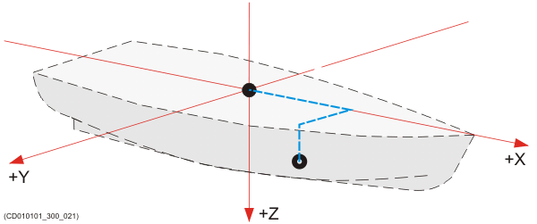
In this example, a second reference point has been established. It is defined with three positive offset values for X, Y and
Z. All values are positive because the new reference point is in front of and below the origin, and on the starboard side.
The accuracy of the three numerical values for X, Y and Z defines the accuracy of the sensor data. If you require a high accuracy, for example for underwater positioning, underwater mapping or scientific measurements, you
must have each sensor positioned using professional land surveying. For such use, a good alignment survey is critical for high quality results. Surveys are normally done by qualified and trained surveyors using proven survey equipment and methods.