Calibration Wizard dialog box #3 (Process Data)
The third page in the Calibration Wizard allows you to import the calibration data into the calibration process. The calibration data recorded are processed consecutively. When the processing is finished, you can save the results, and update the calibration data used by the EK80.
Prerequisites
The Calibration Wizard dialog box can only be opened within the calibration process. In order to start the calibration wizard, the EK80 must be in either Normal or Replay mode.
How to open
To open the Calibration Wizard, place the EK80 in either Normal or Replay mode, and select Calibration on the Setup menu.

In the first Calibration Wizard dialog box, select New calibration from raw data (Real time or Replay). This opens page 2. In the second page of the Calibration Wizard dialog box, select the channel to calibrate and select Next at the bottom of the page.
Description
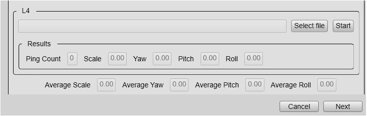
The third page of the Calibration Wizard is used for loading raw data files. The velocity measurements used in the calibration process are stored consecutively in raw data files during the calibration
survey. You select all the raw files from a previous survey in the L1 option on this page. L2 to L4 are left empty.
A progress bar becomes visible in the dialog box during processing.
Details
Select File
Select Select File to open the operator system’s File Manager. In the file manager you select the file(s) for velocity measurement calibration.You select files all the files for calibration and enter in L1.
Start
Select Start to start the calculation of calibration values for a particular line of the ADCP run. A progress bar becomes visible in the dialog box during processing. It disappears when the processing is finished.
Ping Count
Ping Count displays the number of pings being included since the start of the calibration process. The number will accumulate as you process the calibration files for a particular line in the ADCP run.
Scale
Scale refers to the ratio of Speed Over Ground (SOG) from the GPS system versus ADCP. Ideally this value will be close to 1.
Yaw
Adjustment value for vertical rotation of the vessel. The value is based on the pings processed in the calibration.
Pitch
Adjustment value for horizontal rotation around an axis going from side to side of the vessel. The value is based on the pings processed in the calibration.
Roll
Adjustment value for horizontal rotation around an axis going from bow to stern of the vessel. The value is based on the pings processed in the calibration.
AverageScale
Scale refers to the ratio of Speed Over Ground (SOG) from the GPS system versus ADCP. Ideally this value will be close to 1.
Yaw
Adjustment value for vertical rotation of the vessel. The value is based on the pings processed in the calibration.
Pitch
Adjustment value for horizontal rotation around an axis going from side to side of the vessel. The value is based on the pings processed in the calibration.
Roll
Adjustment value for horizontal rotation around an axis going from bow to stern of the vessel. The value is based on the pings processed in the calibration.
Related tasks