Echogram page
The Echogram page allows you to choose which type of echogram you wish to display. You can also control the TVG (Time Variable Gain). The EK80 system can work with several different TVG compensation settings. The TVG (Time Variable Gain) compensation is designed to counteract the natural phenomena of geometric spread and absorption
loss.
Prerequisites
This page is not available when ADCP is activated.
How to open
This page is located in the Echogram dialog box. The Echogram dialog box is located on the Active menu.
Description
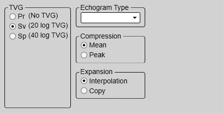
Each separate echogram view offered by the EK80 system can show you a different echogram type. Which type to see is chosen on this Echogram page. The page also allows you to select which TVG curve to use for the chosen echogram.
The Compression and Expansion options are provided to specify how sample data are converted to pixel data.
Note
Before you can change a setting related to a echogram, you must click inside the echogram to activate it. The setting is by default only applied to currently selected echogram. Select Apply to All if you wish to use the chosen settings on all the echograms of the same type.
Tip
You can also select TVG setting with the TVG function. The TVG (Time Variable Gain) function is located on the Active menu.
Details
TVG (Time Variable Gain)
When an acoustic pulse is sent through the water, it will gradually lose its energy. The greater the distance between the transducer and the target(s), the greater the loss of energy.
The TVG (Time Variable Gain) compensation is designed to counteract the natural phenomena of geometric spread and absorption
loss. The TVG compensation is expressed as a logarithmic curve. You can choose from a selection of curves. Each curve has a different slope creating a different gain compensation.
Select the TVG setting you want to use. Several TVG compensation settings are available.
| • | No TVG: TVG compensation is not implemented. This option is hardly ever used. |
| • | Sv (20 Log): Volume backscattering strength |
| • | Sp (40 Log): Point backscattering strength |
Echogram Type
Use this function to select what kind of echogram you wish to see in the current (active) view.
| • | Surface A Surface echogram is mainly used when you wish to look at the entire water column starting from the sea surface and down to the sea
bottom.
Since this echogram is referenced to the sea surface, the sea bottom contour will vary with the actual depth. If you set up the Start Range and Range depths to place the sea bottom contour at the lower end of the echogram, you will have good opportunity to study the echoes
from the water column.
In the surface echogram, all calculations are made from the sea surface and down to the detected sea bottom. Use this echogram type to obtain correct calculation of the biomass. It will also provide valid data for the Target Strength Histogram information pane.
|
| • | Bottom A Bottom echogram is mainly used when you want to examine the echoes from fish close to the sea bottom.
Since this echogram is referenced to the sea bottom, the sea surface will vary with the actual depth, while the bottom is
drawn flat. This makes it easy to study the echoes from the sea bottom. You can investigate the sea bottom conditions and hardness, and detect fish.
The echogram is only drawn for pings that have a successful bottom detection.
|
| • | Pelagic A Pelagic echogram is mainly used when you wish to look at the water column starting from any distance below the sea surface down towards
the bottom, but without seeing the bottom contour.
Pelagic echograms are useful when you work in deeper waters. The reduced range and the fact that you do not need to wait for the bottom echo means that the ping rate is increased.
In a Pelagic echogram the calculations disregard any bottom detection. All calculations are based on the entire echogram shown in the view. If the bottom echo is present in the echogram, the biomass calculation will be wrong.
|
| • | Trawl Trawl sensor systems (such as Simrad PI, PX and ITI) communicate headrope depth, and/or the distance from the headrope to the footrope (trawl opening), to the
EK80 system at regular intervals.
This information is required for the trawl echogram to be generated. The Trawl echogram covers the vertical opening of the trawl with reference to the depth of the headrope. In addition to the trawl opening, the echogram covers a certain range over and under the trawl opening.
The biomass calculations in a Trawl echogram are not restricted by the bottom detection. This means that the bottom echo will be included in the calculations if it appears within the chosen range.
The echogram is only drawn when trawl position information is available.
|
Compression / Expansion
The Compression and Expansion options are provided to specify how sample data are converted to pixel data.
Each ping consists a given number of data samples, where the number of samples is set by the current depth range. This number of samples does not necessarily match the number of vertical pixels in the echogram presentation. The data samples must therefore be compressed or expanded to fit the number of available pixels. In other echo sounders, this function is handled automatically without allowing you to control the process.
| • | Compression The Compression options describe the situation when the number of samples is higher than the number of pixels, and multiple samples are compressed into one pixel.
|
| • | Expansion The Expansion function provides a mean to adjust the presentation when the number of samples is lower than the number of pixels used to
display them. When this happens the sample values must be expanded to match the pixel values.
|
Apply to All
Select Apply to All if you wish to use the chosen settings on all the echograms of the same type.