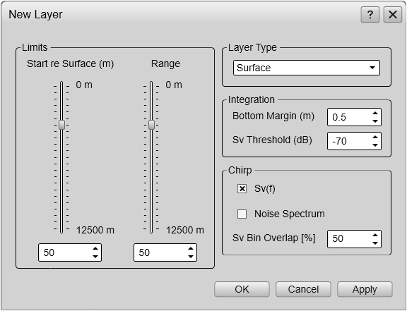
New Layer dialog box
The New Layer dialog box is used to create and insert a new depth layer.

How to open
This dialog box is opened from the Active menu
Description
Different species often occupy different depth layers. Such layers may be defined by salinity or temperature, or simply by
ambient light or the availability of food. In order to study these species, the EK80 supports a Layer function. By means of this function, you can create your own depth layers in the water column to improve the dynamic data
required for analysis.
Layers are used to calculate various values from the echo data collected within a specific depth range in the water column.
By default, a background layer collects all the data from the range chosen on the Main menu. Unless you specify your own layer(s), all data presented by the various information panes are calculated from this
background layer. However, with a large range selected - as in the background layer - the data will not be very accurate.
Once you create your own layer, all calculated values from this layer are displayed in the Numerical information pane. When the layer is selected ("activated") in the Numerical information pane (layer data shown with red text) or in the echogram, all data shown by the relevant information panes are
calculated from the echo data within the selected layer.
Tip
Once a depth layer has been made you can change its properties using the Layer Properties dialog box. If you only wish to change the range settings, you can also click and drag the line(s) in the echogram view.
To delete a layer, select it in the echogram or in the Numerical information field (layer data shown with red text), and then click Delete Layer.
The Numerical information pane is the best tool for controlling your depth layers. All layers are listed, even those that may be located outside your current echogram presentation. The different layers can easily be activated by clicking the list of numerical data.
When a layer is established, it is drawn with two horizontal lines in the echograms. The lines identify the upper and lower
depth settings. If you have only one layer, it will always be "active", and shown with red lines. If you have more than two
layers, the "active" layer is shown with red lines, while the others are shown with black lines.
Details
Limits
Use these settings to control the upper boundary (start depth) and the range of the depth layer.
| • | Start Relative Surface When a Surface or Pelagic layer is chosen, this setting controls the depth at the upper boundary of the layer relative to the surface depth.
|
| • | Start Relative Bottom When a Bottom layer is chosen, this setting controls the depth at the upper boundary of the layer relative to the bottom.
|
| • | Range This parameter controls the vertical depth range for the layer. Positive values are always downwards. A start range relative to bottom of for example -10 m means 10 m above the bottom.
|
Layer Type
You can choose from three different layer types.
| • | Surface The range settings for the layer are referenced to the surface. The layer is downwards limited by the detected bottom depth if this value is shallower than the specified lower range limit
for the layer. "Pings" without a bottom detection are ignored in the calculations.
|
| • | Pelagic The range settings for the layer are referenced to the surface. The layer is not downwards limited by the detected bottom depth.
|
| • | Bottom The range settings for the layer are referenced to the bottom. The layer is downwards limited by the detected bottom depth.
|
Integration
| • | Bottom Margin When you set up the EK80 to measure and calculate echoes from the water column, the bottom echo must be avoided. The strength of this echo will greatly influence the other acoustic measurements. Use the Bottom Margin option to define a vertical depth segment above the detected bottom echo. The data in this segment will not be included in the calculations.
|
| • | Sv Threshold The Sv Threshold option is a filter. It will remove the weakest echoes from the calculations the EK80 do.
Example
If you are bothered by plankton while investigating other species with higher target strength, use the Sv Threshold option to remove the plankton echoes.
|
Chirp
| • | Sv(f) This is an "on/off" switch. This option is by default "on".
The Sv(f) information pane shows you the volume backscatter as a function of the frequency. The information is provided as a plot that shows the how the echo strength for a group of targets (for example a school of
fish) change with the operational frequency. This functionality allows you to identify the nature of the schools, and discriminate between them.
In order to study the targets in a volume of water, we recommend that you confine the targets to a dedicated depth layer to
isolate the interesting echoes. The layer would then for example "highlight" a school of fish. Without this layer the default
background layer will be used, but it may often offer too much data from other echoes.
Extracting and computing the necessary volume backscatter to create the plot in the Sv(f) information pane requires a lot of resources from your Processor Unit. For this reason, you can switch off this functionality for the "active" depth layer. You will then loose the plot in the Sv(f) information pane.
|
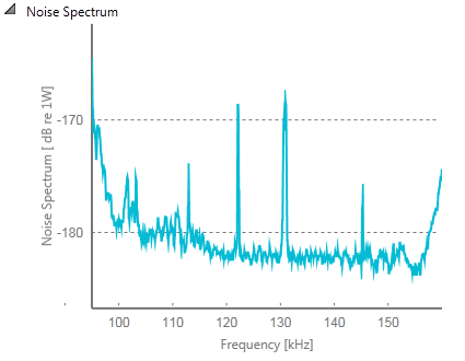
| • | Noise Spectrum This is an "on/off" switch. This option is by default "off".
The Noise Spectrum option displays the current background noise in the echogram view. The noise echoes are not TVG compensated, so they will appear with "true" values on all depths. In most cases, this presentation is only used in passive mode. When activated, a noise spectrum plot is added to the Layer list in the Numerical information pane.
|
| • | Sv Bin Overlap When the EK80 calculates the volume backscatter, it divides the total vertical range of the depth layer to "segments". These segments are stacked on top of each other. The segments may overlap, and the Sv Bin Overlap option controls (in %) how much they overlap.
If you set the value to 0%, they will not overlap at all. This will reduce the computing requirements, but the resulting data will be less accurate. If you set the value to 50% (default value), each part of the segment will be computed twice because of the overlap. At the same time, the computing requirements are acceptable, and the resulting data is accurate.
The Sv Bin Overlap option is not available when the Sv(f) option is disabled.
|