The raw data file format
Each raw data file contains a set of datagrams. The datagrams are in XML, binary or text (ASCII) format. The datagram sequence in the raw data file is not fixed. It depends on the number of installed frequency channels. The files will start with a series of datagrams describing the installed channels. Ahead of the sample datagram sequence there will be a series of NMEA datagram. These are related to the NMEA datagrams received by the EK80 prior to the start of recording. In this context, the term channel is used as a common term to identify the combination of transceiver, transducer and operating frequency.
In order to analyse the raw files you will need to keep in mind some general rules of guidance.
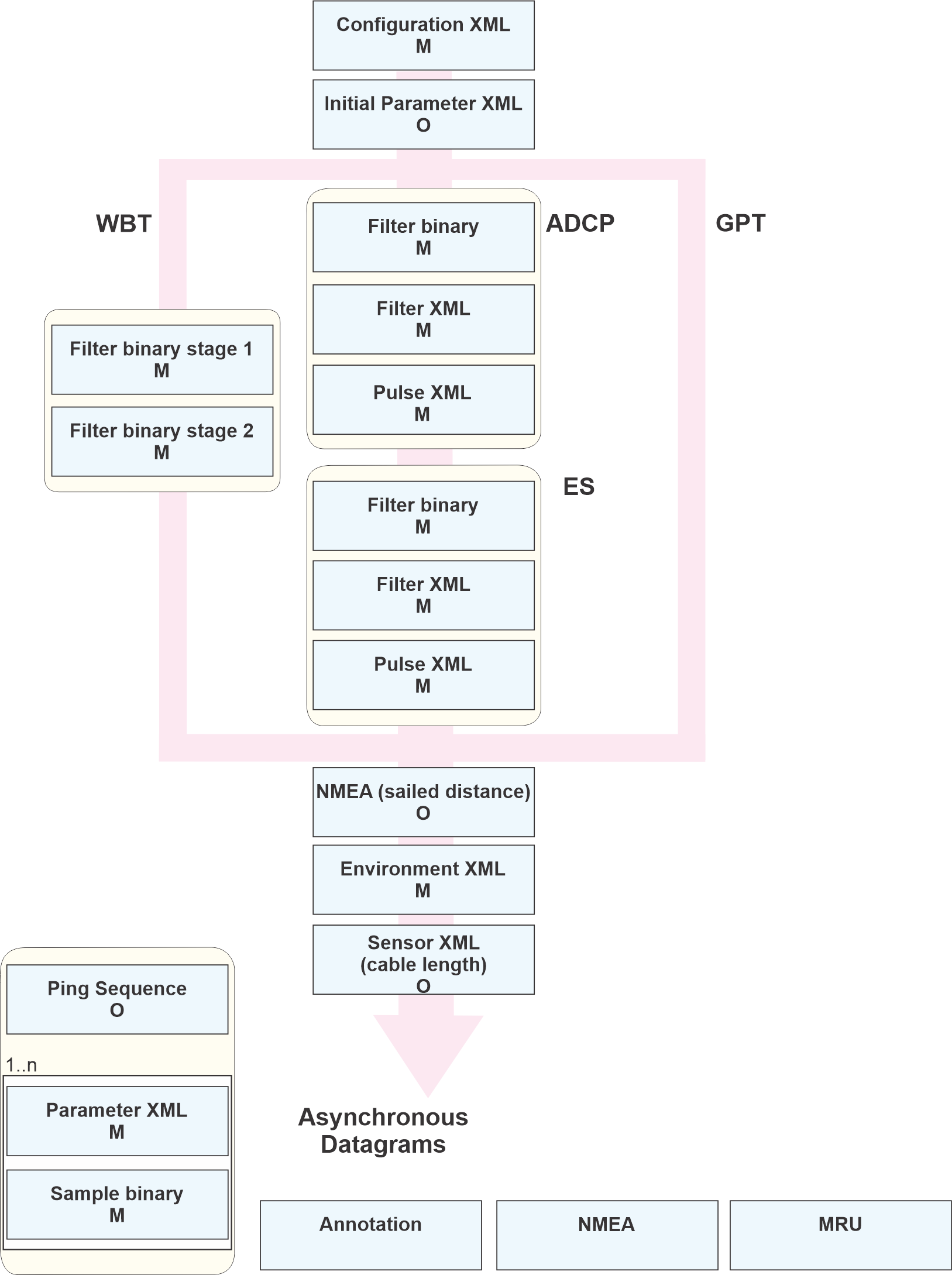
| • | Each raw file starts with a Configuration XML datagram. This is a mandatory datagram The Configuration XML datagram contains parameters that are not subject to change in the file and describes the system used for this recording. |
| • | Some datagrams are mandatory in a raw file, others are optional. Which datagrams are present in your Simrad system depends on the system configuration. |
| • | The datagram sequence in the raw data file is not fixed. Datagrams describing transceiver configuration are recorded in the installation order of the transceivers. Some datagrams are part of a block, others are received asynchronously. |
| • | Filter and pulse datagrams provide configuration information for a transceiver. Some transceiver types have their own block of datagrams for configuration description. Configuration details of all transceivers installed are recorded. |
| • | Sensor and sample datagrams provide information from each channel and ping. The information in the datagrams are linked using the time stamp and the Channel ID information. These datagrams will always be present to provide this information. |

The drawing illustrates the datagrams as they may occur in a raw file. The arrows display the sequence of the datagrams. The raw file starts off with a Configuration XML datagram. Which datagrams that follow is dependent on the type of Simrad system, and also the system configuration. The datagrams for each type of transceiver will differ as displayed in each of the arms in the drawing. The datagrams recorded asynchronous are illustrated at the bottom.
| • | O: Optional |
| • | M: Mandatory |
Transceiver configuration details
Some transceiver types have their own block of datagrams for configuration description. Configuration details of all transceivers installed are recorded.
This is a description of the blocks of configuration datagrams related to each transceiver type. Note that the EK80 system may have any number and combinations of transceivers installed.
Wide Band Transceiver (WBT):

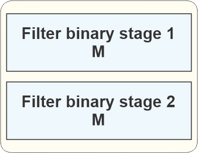
EK80 systems with the Wide Band Transceiver (WBT) (and similar) have two Filter datagrams.The first datagram contains the filter parameters from the transceiver, while the second datagram contains the filter parameters
from the EK80 program. The two filter datagrams have the same structure. They are referred to as "Stage 1" and "Stage 2".
| • | Filter binary datagram This is a binary datagram. The type is FIL1.
The Filter binary datagrams contains filter coefficients used for filtering the received signal.
|
EC150-3C
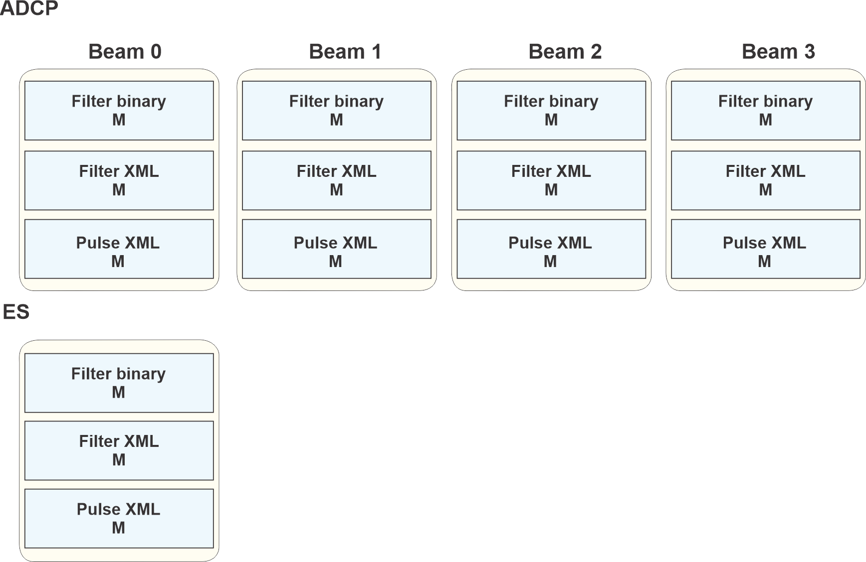
The EC150–3C configuration details include both current profile (ADCP) mode and echo sounder (ES) mode.
The ADCP configuration consists of the following datagrams. There will be one set of these datagrams for each ADCP beam (four in total).

| 1 | Filter binary datagram This is a binary datagram. The type is FIL1.
The Filter binary datagrams contains filter coefficients used for filtering the received signal.
|
| 2 | Filter XML datagram This is an XML datagram. The type is XML0.
The Filter XML datagram contains parameters for filters.
|
| 3 | Pulse XML datagram This is an XML datagram. The type is XML0.
The Pulse XML datagram contains parameters for the transmit pulse.
|
General Purpose Transceiver (GPT)
Installed General Purpose Transceiver (GPT) do not have Filter datagrams.
The GPT has no specific datagrams transmitted for configuration purposes.
Raw format versions versus the EK80 software versions
| Date | Raw format version | EK80 Software version |
|---|---|---|
| 2014.09.11 | 1.01 | 1.8.0 - 1.8.3 |
| 2016.02.18 | 1.10 | Not used |
| 2016.06.09 | 1.20 | 1.10.0 - 1.11.1 |
| 2017.10.02 | 1.21 | 1.12.0 - 1.12.1 |
| 2018.02.01 | 1.22 | Future releases |
| 2020.07.07 | 1.23 | 2.0.0 |
| 2022.01.24 | 1.25 | 22.01 |