4 Collecting data for ADCP calibration
Prerequisites
In order to collect data for velocity measurements calibration the following elements must have been prepared.
| • | The vessel and the EK80 system must be working appropriately. |
| • | All peripheral sensors, including the EC150-3C, must be time synchronized. |
| • | The EK80 must be setup for velocity measurements calibration. |
| • | KM Binary input must be available (from MRU, IMU; MGC, Seapath or other) |
| • | The GPS system must be working appropriately. |
| • | File setup for storage of the raw data recorded must have been prepared. |
| • | Recording of raw data is started. |
Context
Collecting data for calibration is performed by the vessel travelling in a specific pattern, with appropriate operational
settings for obtaining calibration data.
| • | The vessel must strive to keep steady pace. |
| • | Shallow conditions is a preference. |
| • | Depth should be approximately 100 m and the seafloor should be as flat as possible. The depth can deviate from 50 to 200 m. |
| • | The vessel moves in a pattern resembling an "L" while recording data. Each line in the pattern is traversed twice an in opposite directions at a constant compass course. The result will be 4 lines of recorded data. This ensures no directional bias is introduced. |
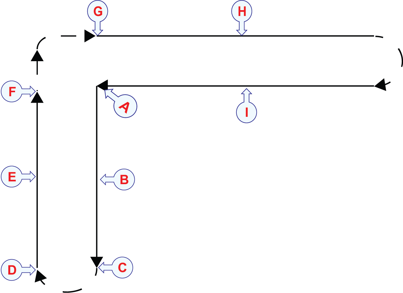
| a | Starting point and finishing point. |
| b | Line #1.The stretch should be 400-800 m. |
| c | Loop in which the vessel turns.In this loop you do not need to record data. |
| d | End of the turn, you can start recording data. |
| e | Line #2 The stretch should be 400-800 m.After a turn, the vessel seeks to survey the same stretch as previously, only in the reverse direction. |
| f | Turn the vessel 90 degrees. In this loop you do not need to record data. |
| g | Line #3 The stretch should be 400-800 m. |
| h | Loop in which the vessel turns.In this loop you do not need to record data. |
| i | Line #4 The stretch should be 400-800 m. After a turn, the vessel seeks to survey the same stretch as previously, only in the reverse direction. |
The ratio of Speed Over Ground (SOG) from the GPS and SOG from the ADCP is used to correct the measurements from the ADCP. Average differences for pitch, roll and yaw are also used to correct the ADCP measurements.
Make sure you validate your data which you have collected and recorded before you proceed to operation.
Procedure
| 1 | Bring the vessel to a stop at the starting point of the first calibration run. |
| 2 | Start recording raw data. |
| 3 | Traverse along a set course and constant compass heading and speed while collecting GPS and ADCP data (raw data) for 400-800 m. |
| 4 | Turn the vessel 180º. Note
At the turning point you can use the file split option in EK80 to create separate files for each line traversed.Alternatively you can stop recording data and resume recording when traversing the next course.
|
| 5 | Traverse along a set course and constant compass heading and speed while collecting GPS and ADCP data (raw data) for 400-800
m. Two ADCP runs in opposite directions are made so that any residual current in the data will be cancelled out.
|
| 6 | Turn the vessel 90º. |
| 7 | Traverse along a set course and constant compass heading and speed while collecting GPS and ADCP data (raw data) for 400-800 m. |
| 8 | Turn the vessel 180º. |
| 9 | Traverse along a set course and constant compass heading and speed while collecting GPS and ADCP data (raw data) for 400-800 m. |
| 10 | Validate your data. |
| 11 | Stop the recording. |
| 12 | Stop "pinging". |
| 13 | Select Save or Save As to save the calibration data. You are not saving raw echo data here, but an XML file that contains the information necessary to run the calibration process.
|
Further requirements
Proceed to the Calibration Wizard for using the collected data to calibrate the EK80 system.