About ramping
The Ramping parameter provided in the Normal Operation dialog box defines how fast the output level of each transmission ("ping") shall increase from 0 V to maximum level. You have two options; Fast and Slow.
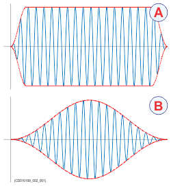
The principle is shown in the illustration. Curve (A) has Ramping set to Fast, and the level is increased from 0 V to maximum level using from minimum two (2) up to maximum ten (10) cycles. At the end
of the pulse, maximum ten down to minimum two cycles are used to reduce the output level.
The number of cycles used depend on the q-factor (bandwidth relative to centre frequency) for the connected transducer. The
number of ramping cycles will be upward limited to the number of cycles in half a pulse length.
Curve (B) has Ramping set to Slow. The output level is increased from 0 V to maximum level using the first half the pulse duration. The second half of the
pulse is then used to reduce the output level.
Advantages
| • | Fast ramping normally means that only the first few cycles of the transmit signal are used to ramp up the signal amplitude and
the last few cycles are used to ramp down the amplitude. For short pulses, the ramping might converge to Slow ramping.
The advantage with Fast ramping is that the transmitted pulse contains more energy relative to the pulse length. This increases the signal/noise
ratio. When you apply "chirp", the transmission frequency changes from a low frequency at the beginning of the pulse to a
high frequency at the end of the pulse. The combination of chirp and Fast ramping will significantly increase the signal/noise ratio.
|
| • | Slow ramping means that the first half part of the transmit signal is used to ramp up the amplitude and the last half part is
used to ramp down the amplitude. The advantage with Slow ramping is that the pulse have a smooth start and stop. This significantly reduces the transients in to the matched filter
and therefore you get reduced side lobes in time (range) at a cost of slightly reduced range resolution at the output of the
matched filter for FM pulses.
The side lobes in time (range) will thus be lower with Slow ramping than with Fast ramping. Smaller side lobes in time (range) will reduce "crosstalk", as a strong echo from one range will not contaminate
weak echoes from other ranges. Increased echo discrimination is particularly useful with echoes of different strength.
|
A raised cosine window is used as ramping function.
| • | Fast ramping will result in maximal received signal power for a longer effective pulse duration and transmit power, and a wider
effective frequency bandwidth than Slow ramping. Fast ramping is normally used to increase frequency bandwidth, range resolution, and signal-to-noise ratio.
|
| • | Slow ramping will result in lower matched filtering side lobes in time (range) than Fast ramping. Slow ramping is normally used to reduce backscatter interference (due to the matched filtering process) between targets closer
to each other than one pulse duration (applies in particular to interference from strong targets on weak targets). Slow ramping increases and decreases the transmit signal amplitude slowly. This is more "gentle" to the transducer and can sometimes
also be used to reduce "ringing" from the transducer.
|
Ramping when using CW transmission
| • | Fast ramping will result in maximal received signal power for a chosen pulse duration and transmit power than Slow ramping. Fast ramping is normally used to increase the signal-to-noise ratio. |
| • | Slow ramping increases and decreases the transmit signal amplitude slowly. This is more "gentle" to the transducer and can sometimes also be used to reduce "ringing" from the transducer. |
Fast ramping is more similar to the ramping type used in the EK60 than Slow ramping.