Normal Operation dialog box
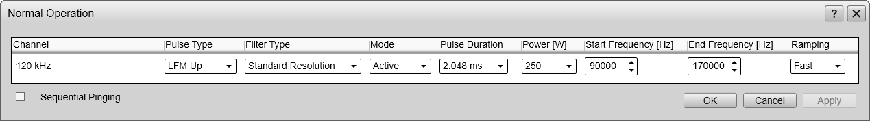
The purpose of the Normal Operation dialog box is to provide you with an overview of the current transceiver parameters. It also allows you to change these parameters to match your current operating requirements.

Prerequisites
The Normal Operation dialog box is only available when the EK80 system operates in Normal mode.
How to open
This dialog box is opened from the Operation menu.
Description
The Normal Operation dialog box lists all the transmission parameters. The dialog box provides one row for each channel in use. In this context, the term channel is used as a common term to identify the combination of transceiver, transducer and operating frequency. You can change the parameters.
If you use a transceiver with multiplexing functionality, the Normal Operation dialog box presents each multiplexed channel separately. Some of the parameters can be chosen individually for each multiplexed channel, other parameters must be common.
Note
The settings in the Normal Operation dialog box are limited by the specifications in the transducer setup file. Therefore, you cannot make any changes that will damage your transceiver or transducer. Certain settings may be limited by your license.
Do not to make any changes unless you are well aware of the consequences.
If you wish to investigate the ambient noise, choose Passive mode in the Normal Operation dialog box. Any noise or disturbance in the water - within the transducer's frequency range - will then be detected and shown. This feature will for example be able to pick up disturbances from other hydroacoustic systems on your own vessel, or on other
vessels in the vicinity.
The EK80 system supports wideband transmissions using frequency sweeps. This is often referred to as "chirp", and means that the transmission frequency changes from a "start" frequency to an "end"
frequency within the transmission. In order to use the frequency sweep ("chirp") functionality, you must use frequency modulated pulses. You must also use a transducer that supports the frequency range.
Some of the information provided in the Extras menu reflects the settings in the Normal Operation dialog box.
Note
Some of the settings are specific for echo sounder or ADCP operation. The following ADCP systems are currently supported:
| • | Simrad EC150-3C The EC150-3C is a dual purpose unit. It can be used either as an acoustic Doppler current profiler (ADCP) instrument to measure water current or as a split-beam echo sounder. It can not operate these two functions simultaneously.
|
Details
Channel
This column identifies the channel. In this context, the term channel is used as a common term to identify the combination of transceiver, transducer and operating frequency. The text string provides the following information:
| • | Transducer name |
| • | Transducer serial number |
If you use a transceiver with multiplexing functionality, the Normal Operation dialog box presents each multiplexed channel separately. Some of the parameters can be chosen individually for each multiplexed channel, other parameters must be common.
Pulse Type
The Pulse Type function allows you to select the "shape" of the transmitted pulses ("pings").
| • | CW |
| • | LFM |
The abbreviation "CW" means "Continuous Wave". "LFM" means "Linear Frequency Modulated".
In LFM Down the transmitted pulse starts using the upper frequency in the range, and ends with the lower frequency. The frequency sweep is linear. In LFM Up the transmitted pulse starts using the lower frequency in the range, and ends with the upper frequency.
Note
In order to use the frequency sweep ("chirp") functionality, you must use frequency modulated pulses. You must also use a transducer that supports the frequency range.
Only the Wide Band Transceiver (WBT) supports LFM Down. Your WBT must be fitted with the latest software version.
You can only use LFM Down on one channel on each transceiver. Any attempt to try these modes on more than one channel will result in an error message.
Filter Type
A dedicated receive filter is available. This filter setting is only available for LFM pulses.
Standard Resolution
This filter setting applies the same bandpass filters and decimations as for the previous EK80 software versions.
Short
This filter setting applies short bandpass filters and the lowest possible decimation. This setting will generally result in a shorter impulse response and higher output sample rate. These resulting echo data can be used to address range sidelobe issues from the bandpass filters while examining targets near
boundaries. Note that the filter is wider in frequency, and may result in a reduced signal-to-noise ration.
Note
Unless you need the short resolution due to boundaries we suggest that you use the standard resolution. This setting reduces both the noise and the amount of data We recommend that you calibrate the EK80 system with the Filter Type setting that you will use during the survey.
We regard the receive filter as "experimental" and invite you to review the results.
This functionality is not available for ADCP operation.
Mode
This column specifies the current transceiver mode. You can manually select the mode that suits your current operation.
The following modes are available:
Passive
In Passive mode, the EK80 system will only receive and compute the signals detected by the transducer(s). This mode is useful for test purposes, and when you want to measure the ambient background noise in the sea. It can be useful to run the EK80 system in Passive mode to discriminate between target echoes (present only in Active mode) and noise (present in both Active and Passive modes).
Pulse Duration
The Pulse Duration setting specifies the current duration ("length") of the transmitted pulse. You can manually select a pulse duration that suits your operation.
The pulse duration can be selected according to the current depth and what kind of fish you are looking for. The deeper you wish to see, the longer pulse duration should be selected. However, when using CW transmissions a long pulse duration will reduce the resolution. It will also cause the EK80 system to transmit less frequent. Remember that in the EK80 system, the pulse duration and the bandwidth are mutually dependant.
For CW (Continuous Wave) transmissions:
| • | Long pulses provides longer detection range. They make the EK80 system less sensitive for noise, but offer lower range resolution. |
| • | Short pulses provides shorter detection range. They make the EK80 system more sensitive for noise, but offer higher range resolution. |
For FM (Frequency Modulated) transmissions:
| • | Long pulses provide longer detection range, and the range resolution is independent of the pulse duration.. |
| • | Short pulses provide shorter detection range, and they make the EK80 system more sensitive for noise. |
The current setting of this parameter is also shown in the Extras menu.
This functionality is not available for ADCP operation.
Power
You are permitted to adjust the output power of the EK80 system. You can not increase the power to beyond the transducer’s capacity, but you may reduce it for better performance in shallow
water, or if you are struggling with reverberation.
The Power parameter in the Normal Operation dialog box displays the transmitter's output power measured in Watts. You can change the output power manually. Output power is limited either to the maximum rating of the transducer, or the maximum rating of the transmitter, whichever
is the smallest. For all practical purposes, this means that you can reduce the power output, but you can not increase it to beyond the power rating of the transducer.
The current setting of this parameter is also shown in the Extras menu.
Start/End Frequency
The Start Frequency and End Frequency parameters are used to set up a frequency sweep ("chirp"). If the parameters for start and end frequencies are unavailable, the transducer used on the relevant channel does not support
wide band transmissions. In order to use the frequency sweep ("chirp") functionality, you must use frequency modulated pulses. You must also use a transducer that supports the frequency range.
Note
It is very important that the transducer you use complies to the frequencies you choose. The frequency range of each transducer is defined in the transducer setup file. If you choose a frequency range that is not supported, and error message will appear.
The current setting of this parameter is also shown in the Extras menu.
This functionality is not available for ADCP operation.
Ramping
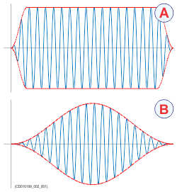
The Ramping parameter provided in the Normal Operation dialog box defines how fast the output level of each transmission ("ping") shall increase from 0 V to maximum level. You have two options; Fast and Slow.
The principle is shown in the illustration. Curve (A) has Ramping set to Fast, and the level is increased from 0 V to maximum level using from minimum two (2) up to maximum ten (10) cycles. At the end
of the pulse, maximum ten down to minimum two cycles are used to reduce the output level.
The number of cycles used depend on the q-factor (bandwidth relative to centre frequency) for the connected transducer. The
number of ramping cycles will be upward limited to the number of cycles in half a pulse length.
Curve (B) has Ramping set to Slow. The output level is increased from 0 V to maximum level using the first half the pulse duration. The second half of the
pulse is then used to reduce the output level.
The current setting of this parameter is also shown in the Extras menu.
This functionality is not available for ADCP operation.
Sequential pinging
The Sequential pinging function can be used if you have more than one channel in use on the EK80 system. When activated, each individual transceiver will transmit ("ping") in sequence, one by one. When not activated, all transceivers will "ping" simultaneously.
If two transducers are used on a transceiver, these will also "ping" simultaneously.
Tip
The Sequential pinging function can be very useful if your transducers are located in such a manner that interference is a problem.
The current setting of this parameter is also shown in the Diagnostics dialog box. You open the Diagnostics dialog box from the Setup menu.
This functionality is not available for ADCP operation.
Max(imum) Current Speed
Maximum Current Speed controls the pulse duration and the processing functionality for ADCP operation. You do not need to make frequent changes to this setting. Select a value based on the expected water currents in your survey area. If you are uncertain, choose a value above the expected water current, and reduce it based on experience. The value you choose must always be equal or larger than the expected value.
Note
The measurement accuracy is reduced if the value is set much too large.
Depth Cell Size
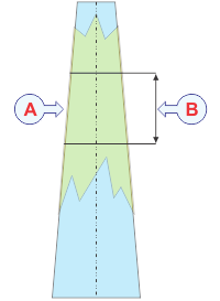
In water current measurements, the phrase cell is used to describe a depth cell. A depth cell is defined by its vertical length, Depth cell size, measured in meters.The Depth cells size is adapted to the acoustic pulse length. These are uniform segments used by the acoustic Doppler current profiler (ADCP) to measure the velocity of the current.
The acoustic Doppler current profiler (ADCP) measures the speed and direction of the water current by means of acoustic pulses. These pulses have duration decided by the current size of the depth cell. Each beam can be seen as a number of depth cells evenly placed from the transducer surface and down to the lower end of the
acoustic beam.
| • | Use smaller depth cells in shallower waters. |
| • | Use larger depth cells in deeper waters. |
A small depth cell offers better range resolution. This makes it is easier to detect minor depth variations in the current velocity. On deeper waters, a small depth cell will gradually suffer from more and more noise. The ping rate will also be reduced due to the high amount of processing that is required. A larger depth cell tolerates more noise. For this reason, larger depth cells must be used to measure velocity in deep waters.
This functionality is only available for ADCP operation.