Current velocity
Water current velocity is measured in each of the beams of the ADCP transducer. Through processing the velocities relative to the vessel (Vessel Velocity) and to earth coordinates (Geographical) are calculated. The effect of the vessel speed is removed from the measured velocities. The result is water current velocity estimates throughout the entire water column of the beams.
The most important feature of any ADCP sensor is its ability to measure current profiles and current velocities. The sensor
divides the velocity profile into uniform depth cells (bins). By means of the sliding average method it creates a current
velocity profile of the water column. A number of factors and processes are involved in this measurement.
Relative velocity between sea and transducer is measured in each of the four beams. Each beam can only measure the velocity along the beam. Like a telescope with a narrow focus, it can only "see" things along its line of sight. This may be towards the ADCP transducer or away from it, but only along the beam.
This velocity is referred to as beam velocity. The beam velocity is estimated through the water column in the beam using uniform depth cells along the beam. The acoustic transmissions emitted by the transducer produce echoes, and these are retuned to the receiver. These echoes are subjected to a Doppler shift, and provide information about the current velocity. In order to create a current velocity profile echoes from the entire range of the beam must be processed by the receiver. This involves continuous processing of the echo data. Echoes from larger ranges take longer to return than echoes from closer ranges.
Tip
The size of the depth cells can be adjusted in the Normal Operation dialog box.
| • | Use smaller depth cells in shallower waters. |
| • | Use larger depth cells in deeper waters. |
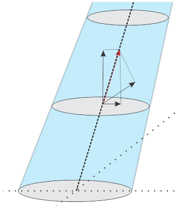
Illustration:
Each measurement of the water current velocity is presented as a vector drawn as an arrow. The length of the arrow indicates the velocity of the water. The tip of the arrow indicates the direction. The current velocity can be broken down into components in three dimensions. Displaying the horizontal and vertical component of the current velocity provides a visualisation of the displacement of the
current in these directions. This is useful in order to estimate the relative current velocity in the cardinal directions or relative to the vessel orientation,
as well as to estimate the current velocity in the up/downward direction. GPS and MRU data are used to find the transducer's velocity.
The beam velocities along the four beams are combined to find the two horizontal and the vertical velocity components, in
addition to the error velocity. Knowledge about the installation angles of the transducer makes it possible to transform the estimated velocity to vessel
coordinates. Data from MRU and GPS (roll, pitch and heading) are used to transform the velocity to global coordinates. Since the ADCP measured velocity at this stage is the relative velocity between sea and transducer, transducer's velocity
has to be removed to get the current velocity. The transducer's velocity is removed, and the output is the current velocity in global coordinates.