Extras menu
The Extras menu is - in spite of its name and location - not a menu at all. This "menu" opens a small view to monitor key operational parameters.
How to open

Select the Extras icon. The icon is located under the Main menu. Select the icon one more time to close the menu.
Description
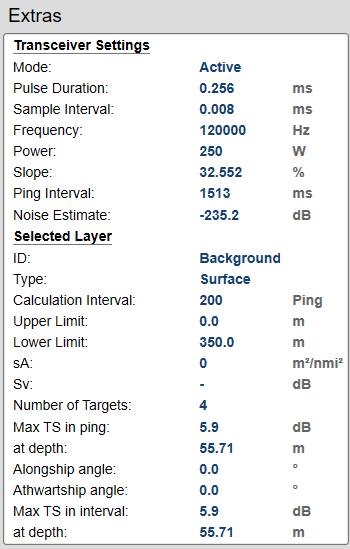
The Extras "menu" gives you an overview of the main operational parameters. The information is based on the currently "active" echogram.
Additional information is added about the currently "active" layer. In this context, the phrase layer is used to describe the depth layers that may be defined for the EK80 echograms. Each layer is defined by its upper and lower depth limit.
Note
Some of the settings are specific for echo sounder or ADCP operation.
Transceiver settings
Mode
The operating mode is controlled by Operation on the Operation menu. You can set it to Normal, Replay or Inactive. To activate the Advanced Sequencing operating mode an operational sequence must have been created previously. This information is also provided in the Numerical information pane.
Pulse Duration
The Pulse Duration setting specifies the current duration ("length") of the transmitted pulse. You can manually select a pulse duration that suits your operation.
This setting is controlled in the Normal Operation dialog box.
This information is also provided in the Numerical information pane.
Sample Interval
The information from the transducer on the EK80 system is a continuous flow of analogue data. In signal processing, sampling is the reduction of this continuous signal to a discrete signal.We convert a sound wave (which is an analogue continuous-time signal) to a sequence of samples (which is a discrete-time signal). The sample rate is the average number of samples obtained in one second. The sample interval is 1/sample rate to allow readout in time (normally milliseconds).
This information is also provided in the Numerical information pane.
Frequency
This setting is controlled in the Normal Operation dialog box. The Start Frequency and End Frequency parameters are used to set up a frequency sweep ("chirp"). If the parameters for start and end frequencies are unavailable, the transducer used on the relevant channel does not support
wide band transmissions. In order to use the frequency sweep ("chirp") functionality, you must use frequency modulated pulses. You must also use a transducer that supports the frequency range.
Power
The Power parameter in the Normal Operation dialog box displays the transmitter's output power measured in Watts. You can change the output power manually. Output power is limited either to the maximum rating of the transducer, or the maximum rating of the transmitter, whichever
is the smallest.
Slope
The Slope value identifies how fast the output power in each transmission ("ping") goes from 0 to maximum. The value (in %) indicates the amount of the pulse duration that is spent during this increase. For example, if the Slope value is 50%, it means that half the duration of the "ping" is spent building up the power to maximum.
Ping rate
The phrase ping rate is used to describe the parameter that controls how often the EK80 system can or shall transmit acoustic energy (a "ping") into the water. The ping rate is normally limited by the maximum range settings. It also depends on hardware limitations. This may be, for example, how fast your EK80 system can handle the information from each ping, how fast it communicates with external peripherals, or how long time it
uses to save data.
The ping interval (1/ping repetition frequency (PRF)) is the ping rate measured in time between each acoustic transmission.
This information is also found in the Diagnostics dialog box. You open the Diagnostics dialog box from the Setup menu.
Noise Estimate
This value reflects an estimation of the noise level over the transducer bandwidth. For every transmission ("ping") the EK80 system measures the echo levels along the chosen range. Typically, these measurements are made every five meters, even for long ranges.
All echoes and noise in the water are recorded. This includes noise generated by your own vessel (electric, propellers, machinery etc), water flow, cavitation and interference. Echoes from fish and other species, as well as from the bottom, are detected and added to the equations.
By comparing these measurements, the EK80 system calculates a noise estimate.
Tip
If you set the EK80 system to Passive mode, all echoes from the transmissions are removed from the equations. This gives you with better information about the
actual noise. If you want to switch to Passive mode, use the Normal Operation dialog box. The Normal Operation dialog box is located on the Operation menu.
This information is also found in the Diagnostics dialog box. You open the Diagnostics dialog box from the Setup menu.
Depth Cell Size
This setting is controlled in the Normal Operation dialog box.
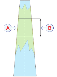
| A | Depth cell |
| B | Depth cell size |
In water current measurements, the phrase cell is used to describe a depth cell. A depth cell is defined by its vertical length, Depth cell size, measured in meters.The Depth cells size is adapted to the acoustic pulse length. These are uniform segments used by the acoustic Doppler current profiler (ADCP) to measure the velocity of the current.
The acoustic Doppler current profiler (ADCP) measures the speed and direction of the water current by means of acoustic pulses. These pulses have duration decided by the current size of the depth cell. Each beam can be seen as a number of depth cells evenly placed from the transducer surface and down to the lower end of the
acoustic beam.
| • | Use smaller depth cells in shallower waters. |
| • | Use larger depth cells in deeper waters. |
A small depth cell offers better range resolution. This makes it is easier to detect minor depth variations in the current velocity. On deeper waters, a small depth cell will gradually suffer from more and more noise. The ping rate will also be reduced due to the high amount of processing that is required. A larger depth cell tolerates more noise. For this reason, larger depth cells must be used to measure velocity in deep waters.
This functionality is only available for ADCP operation.
Max(imum) Current Speed
This setting is controlled in the Normal Operation dialog box.
Maximum Current Speed controls the pulse duration and the processing functionality for ADCP operation. You do not need to make frequent changes to this setting. Select a value based on the expected water currents in your survey area. If you are uncertain, choose a value above the expected water current, and reduce it based on experience. The value you choose must always be equal or larger than the expected value.
Note
The measurement accuracy is reduced if the value is set much too large.
This functionality is only available for ADCP operation.
Maximum Vessel Speed
ADCP operations cannot take place without input from a motion sensor. The input must be provided on the KM Binary datagram format.
KM Binary is a proprietary datagram format created by Kongsberg Maritime for general use. This format has very high resolution on timing and sensor parameters. The datagram is provided by a compatible motion reference unit (MRU). If the KM Binary datagram is successfully received, the displayed value is 0.0 knots.
Selected layer
Id (identification)
This value identifies the layer.
Type
This functrion identifies the echogram type in use.
Calculation Interval
The Calculation Interval settings define the parameters that are used to calculate the biomass and the size distribution. You can base the calculations on sailed distance, elapsed time, or a number of pings. The current parameter setting is shown.
The Calculation Interval parameters can accessed from two places in the user interface.
| • | The page is opened in the Information Pane Options dialog box. |
| • | The dialog box is opened using the Calculation Interval button on the Setup menu. |
The parameters are the same, it does not matter if you use the page or the dialog box.
Upper Limit / Lower Limit
These parameters identify the depth range covered by the layer.
sA
sA is the nautical area scattering coefficient. In this context the sA value presents the current biomass index. sA is commonly abbreviated as NASC.
Sv
Sv is the volume backscattering strength. Sv is commonly abbreviated as VBS. The Sv value identifies the total volume backscatter in the depth layer.
Number of targets
This information identifies the number of individual targets (single fish) in the depth layer.
Max TS in interval ... at depth
These parameters identify the strongest target strength detected, and at which depth.
Alongship angle / Athwartship angle
These parameters identify the alongship and athwartship offset angles for the transducer. These offset angles are taken from the calibration results.
Noise Spectrum
This information is only valid for FM transmissions. The value reflects an estimation of the noise level over the transducer bandwidth. This information is useful for identifying noise sources in both Passive and Active transmission modes.