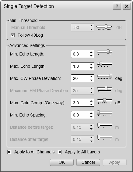
Single Target Detection dialog box
The Single Target Detection parameters are used to control the operational settings for the detection of single targets. In order to detect single fish correctly, these parameters must be defined to suit the target characteristics. The chosen settings do not have any effect on the raw data you save during the survey.
How to open
This page can be opened from several places in the user interface.
| • | The dialog box is opened from the Active menu |
| • | The page is opened in the Information Pane Options dialog box. To open the Information Pane Options dialog box, select the button on the Active menu. You can also select the Setup button in the relevant information pane.
|
| • | The Single Target Detection dialog box can be opened from the third and fourth pages in the Calibration wizard. In order to start the wizard, the EK80 system must be in either Normal or Replay modes. |
Description
Several specific parameters are available for studies of single fish. In order to detect single fish correctly, these parameters should be defined to suit the target characteristics.
Note
The choices you make have no effect on the raw data you record. The settings are only used during the real-time presentation of the data.
During calibration, the settings are used to maximize the detection of the calibration sphere, and suppress other echoes in
the calibration layer.
When opened, the choices provided reflect the current operational settings. Certain options may therefore be unavailable.
Details
Minimum Threshold
This setting applies to both CW and FM operation.
Some echoes are stronger than others. If you have noise problems, or you are bothered with for example smaller fish (different species), jellyfish or plankton,
you can use the Minimum Threshold function to adjust the sensitivity. The target strength (TS) for a single target must exceed this threshold (in dB) to be accepted.
Use this function to define a "filter" value.
Follow 40 Log
Select this option to let the threshold follow the minimum level defined on the Colour Scale page for the corresponding channel.
Minimum Echo Length / Maximum Echo Length
These settings only apply to CW operation.
The echo from a single target will normally have a similar (or slightly longer) length than the length of the transmitted
signal. This is due to the physical properties of the target.
Some single targets are so close in range that they are overlapping. These will give you a longer echo than the length of the transmitted pulse. It is important that such multiple targets are excluded. By using the echo length values, you can define the maximum and minimum length of the echo compared to the transmitted pulse. If the echo is too long or too short, it will be excluded.
Example
If you set Minimum Echo Length to 0.8, all echoes shorter than 0.8 times the length of the transmitted pulse will be deleted.
If you set Maximum Echo Length to 1.8, all echoes longer than 1.8 times the length of the transmitted pulse will be deleted.
Maximum CW Phase Deviation
This setting only applies to CW operation.
Several single targets occurring at the same range will give you echoes in different parts of the beam’s cross section. All samples in an echo from a single target will normally have similar phase value (angles) as the samples arrives from the
same location. Echoes from multiple targets or random noise will show great variation in phase.
To remove the bad targets, the angle (phase) between the samples in the echo are measured. If the angle is too large, the echoes are deleted.
Maximum FM Phase Deviation
This setting only applies to FM operation.
Several single targets occurring at the same range will give you echoes in different parts of the beam’s cross section. To remove the bad targets, the angle (phase) between the samples in the echo are measured. If the angle is too large, the echoes are deleted.
If the angle at a given range is too large, this indicates multiple targets.
Maximum Gain Compensation
This setting applies to both CW and FM operation.
Not all single targets are located in the centre of the beam. Targets located off centre will offer weaker echoes due to the beam properties. The EK80 system automatically compensates for this using a mathematical model, and you can manually control the effect of this algorithm
by defining a maximum gain value.
Using the 3 dB setting all echoes from within the nominal beam width of the transducer will be accepted. By reducing the value, you will only accept echoes that appear closer to the centre of the beam. Reducing the value of this parameter will effectively narrow the beam opening angles for single target detections, but will
normally improve the accuracy of the target strength values for the detected single targets.
Minimum Echo Spacing
This setting only applies to CW operation.
This parameter defines the minimum distance between two single echoes when you are using CW pulses. If they are too close, the echoes are skipped.
The distance is defined as a relation to the length of the transmitted signal. Selecting 1 means that the minimum spacing corresponds to the physical distance covered by the transmit pulse. Increasing the value will require the targets to be further separated, but can improve the accuracy of the target strength
values.
Tip
Overlapping targets will not be identified with this function. Use the Minimum Echo Length, Maximum Echo Length and Maximum CW Phase Deviation to handle these.
Distance Before Target / Distance After Target
These settings only apply to FM operation.
The Distance Before Target and Distance After Target settings define the required spacing before and after one target to the end and beginning of the next target. This is the same functionality as the Minimum Echo Spacing function for CW operations, but the algorithms are very different.
They also define the range of target samples which are used for Fourier transformation to create the target strength frequency
response (the curve in the TS(f) information pane) and the target position phase values.
Increasing the distance values will require the targets to be further separated, but can increase the frequency resolution
for the target strength frequency response (in the TS(f) information pane).
The value for the Distance After Target should normally be larger than the value for Distance Before Target due to the backscattering properties of a target. The values are specified in meters and are applied on the matched filtered/pulse compressed sample data.
Apply to All Channels
Check this box to apply the current setting to all the channels on your EK80 system. In this context, the term channel is used as a common term to identify the combination of transceiver, transducer and operating frequency.
Apply to All Layers
Check this box to apply the current setting to all the depth layers on your EK80 system.