Transducer Installation page
The transducers you want to use with the EK80 system must be "installed" as a part of the software configuration. Which transducers to use depends on the number of transceivers in your system, and the licenses you have for these. Unless you replace a broken transducer, or add a new, you only need to do this once.
Prerequisites
Several of the pages in the Installation dialog box are not available when your EK80 system is set to Replay mode.
How to open
This page is located in the Installation dialog box. To open, select it on the Setup menu.

Description
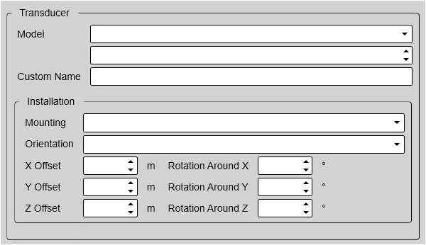
Each transducer to be added to the EK80 system must be selected and identified individually.
You can only choose a transducer from the Model list. When the transducer is selected, you must provide its serial number, and type a name that you choose yourself. Once a transducer has been installed, it is listed in the Installed Transducers box. To see the information you have collected about the transducer, select the relevant transducer in the list.
Tip
Just making changes and selecting OK at the bottom of the page will not install anything. Select what to install, define the relevant parameters, and then select Add.
Once a transducer has been installed, you can verify its operational condition in the Diagnostics dialog box. Open the Diagnostics dialog box from the Setup menu. By means of the Transducer page you can check the impedance of each transducer during normal operation. Any errors are then easily detected.
If your EK80 system shall only be used with an ADCP transceiver or transducer for current profiling, you do not need to install other
transducers.
Details
Installed Transducers
Model
When you add a new transducer, you can only choose a transducer from the list.
The list is generated from a system file on your computer. It contains all the transducers that are compatible with the transceiver, but since the software is common for several systems
there may also be non-compatible transducers in the list. The list also includes technical specifications for each transducer. You can not see this information, but it is used by the EK80 system to set up the operational parameters. This allows the transceiver to optimise its performance for the individual transducer models.
If you cannot find your transducer in the list, contact you dealer to upgrade the relevant software component.
Serial number
Custom Name
Type any name that you wish to use to identify the transducer. The name you select will only be used to identify the transducer in other dialog boxes. It is not used in the echo data that you export.
Tip
If you do not have a computer keyboard connected to your EK80 system, select the Keyboard button to open an on-screen keyboard.
Mounting
Transducer(s) mounted in a towed body are supported. The towed body must include a suitable depth sensor providing the current depth in an NMEA DPT datagram. In this datagram, the second depth value (offset, in meters) must contain the towed body depth. The sensor is connected to a communication port on the computer.
If you are installing a transducer mounted in a towed body, select Towed.
| • | Set Orientation to Vertical. |
| • | Set the vertical installation offset (Z Offset) to the distance between the transducer and the depth sensor in the towed body. |
The depth of the towed body is shown in the Numerical information pane.
Tip
In some EK80 system applications, one or more transducers are installed facing upwards. In order to adjust the echogram presentations to this use, the Beam Direction function is introduced. Unlike the presentation on a traditional fish finding echo sounder, you can select Upwards mode. The presentation is then adjusted for a transducer located at the bottom of the echogram looking up towards the sea surface.
Orientation
Offsets
The physical location of the transducer is important for the echo data accuracy. Use the centre of the transducer face as reference, and define the offset values related to the Ship Origin.
Note
These settings are intended for the installation of an ADCP transceiver or transducer for current profiling. The information is not used to adjust for installation misalignments, but will be included in the RAW files for post-processing
purposes.
X Offset
Y Offset
Rotation
The Rotation angles can be used whenever required to compensate for a rotational offset. These settings are intended for the installation of an ADCP transceiver or transducer for current profiling.
Note
These settings are intended for the installation of an ADCP transceiver or transducer for current profiling. The information is not used to adjust for installation misalignments, but will be included in the RAW files for post-processing
purposes.
Rotation Around X
Rotation Around Y
Example
Split-beam transducers have a notch or mark to indicate forward direction. The sectors in the split-beam transducer refer to this forward direction. It is therefore very important that the transducer is installed as indicated by the arrow and the physical guide cam on the
transducer body. If a transducer may has been installed out of alignment you can compensate by adjusting Rotation Around Z.
Connection
A split-beam transducer with four sectors can be physically connected to the transceiver to work as a single-beam transducer. If you have made this connection, you must tick this box to make the EK80 system operate accordingly. The relevant wiring is described in the Installation Manual.
Note
You must change the wiring in the transducer plug!
Add
Edit
The Edit functionality on the Transducer Installation page makes it possible to change the information you have provided for the transducer. You cannot change the model identification and the serial number. Select Edit to make the relevant changes. Select Apply Changes to save the changes you have made.
Remove
The Remove functionality on the Transducer Installation page makes it possible to delete the information you have provided for the transducer.
Note
There is no "undo" functionality. When you remove a transducer from the EK80 system configuration, you also delete all calibration information. If you later wish to re-install the same transducer, the calibration must be repeated.