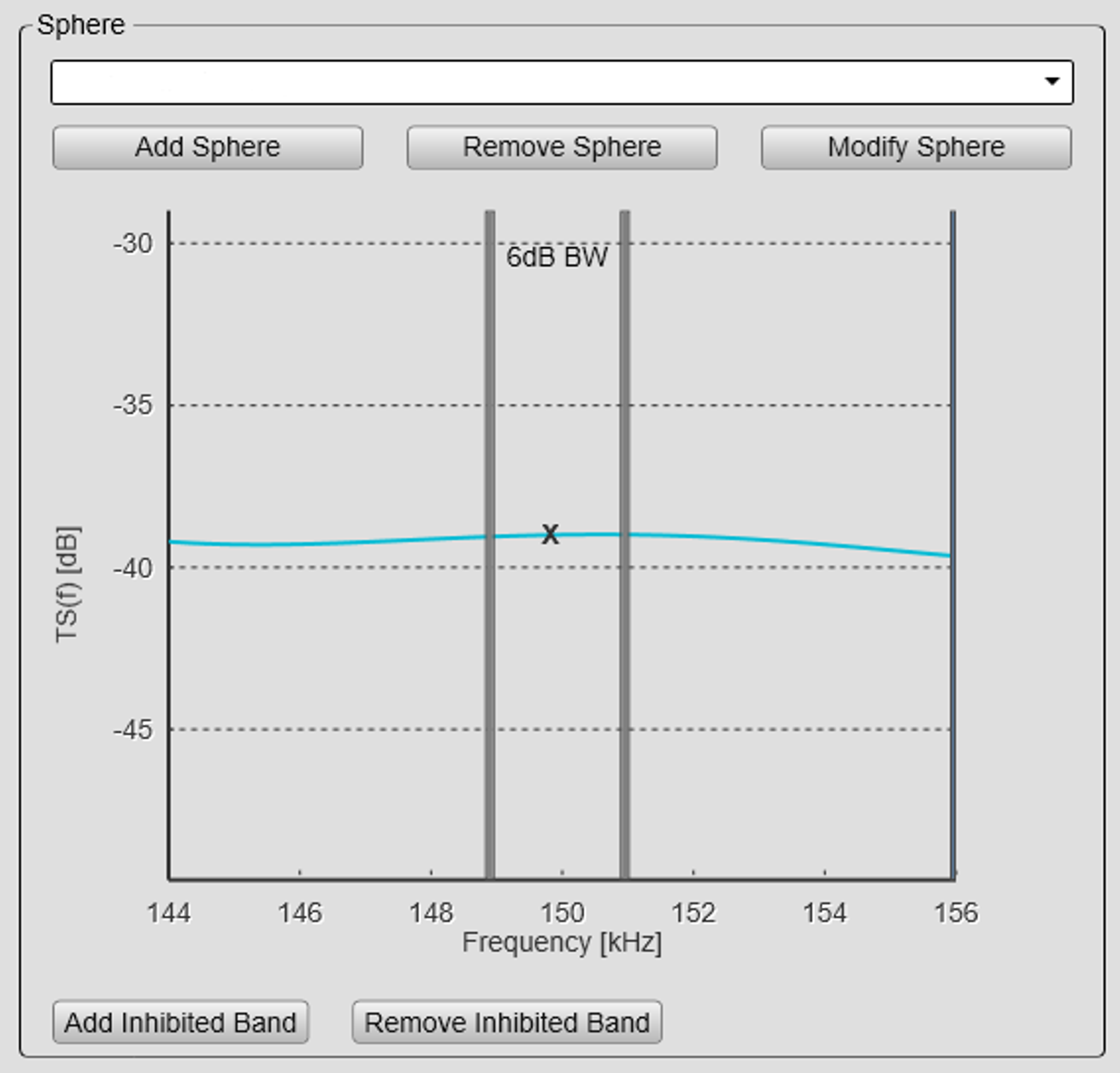
Calibration Wizard dialog box #3 (Select Sphere)
In the third page of the Calibration Wizard you choose the calibration target (sphere). You can also add or delete spheres, and modify the parameters.
Prerequisites
The Calibration Wizard dialog box can only be opened within the calibration process. In order to start the calibration wizard, the EK80 must be in either Normal or Replay mode.
How to open
To open the Calibration Wizard, place the EK80 in either Normal or Replay mode, and select Calibration on the Setup menu.

In the first Calibration Wizard dialog box, select New calibration from raw data (Real time or Replay). This opens page 2. In the second page of the Calibration Wizard dialog box, select the channel to calibrate and select Next at the bottom of the page.This opens page 3.

Note
For Continuous Wave (CW) pulses the bandwidth is indicated by the two solid lines. Select a sphere with an acceptable flat response within this band of frequencies.
Description
Calibration spheres are provided in different sizes to fit different operational frequencies. They are also manufactured from different materials, mainly Copper (Cu) and Carbide (TC). The latter is also referred to as
Wolfram carbide (Wo-Co). "Co" is short for Cobalt, which is used as binder in the sphere.
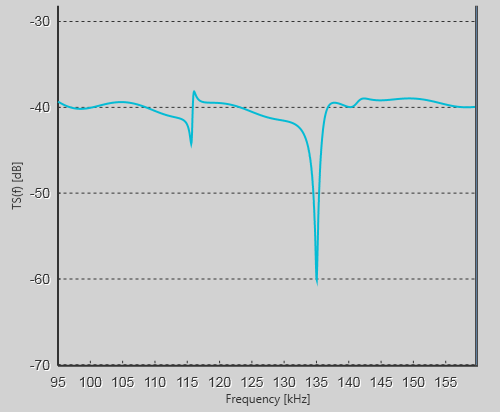
For the currently selected sphere, the Calibration Wizard page four presents a curve that shows the relationship between the operational frequency and the sphere's target strength. The shape of the curve tells you if the characteristics of the selected sphere disqualifies it from use within specific frequency
bands due to low target strength. The functionality of the curve allows you to adjust the frequency band(s), while the Add Inhibited Band and Remove Inhibited Band buttons allow you to define upper and lower frequencies for which the calibration can take place.
Tip
To add or edit spheres, and to control their operative parameters, see the Add/Edit Sphere dialog box.
National Oceanic and Atmospheric Administration (NOAA) provides a web based sphere target strength calculator on the following
URL: http://swfscdata.nmfs.noaa.gov/AST/SphereTS
Adjusting the frequency bands
Due to their unique characteristics, the various calibration spheres offer different target strengths when the frequency changes. This is clearly seen when you calibrate in FM using a larger frequency band. If the shape of the curve shows significant differences in the target strength, the calibration using the related frequency
band(s) will be inaccurate.

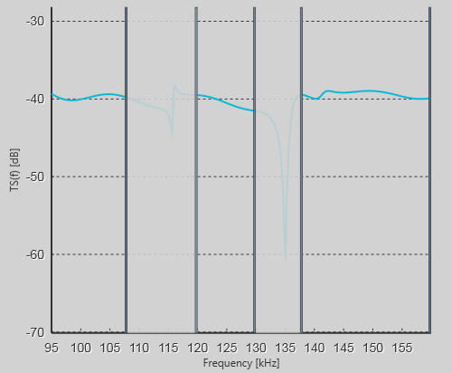
You can remove one or more frequency bands from the calibration processing. This is done by defining "stop bands". The EK80 is not calibrated for the frequencies inside the chosen frequency band. The software in the EK80 will instead interpolate calibration values.
| • | Select Add Inhibited Band, then select a spot on the curve to add a frequency band to the TS/Frequency curve. Only the frequencies outside this band will be used for calibration. |
| • | Select Remove Inhibited Band, then select a band on the curve to delete it from the TS/Frequency curve. |

As an alternative, you can do the entire calibration one more time using another sphere. The results from the second calibration must then be merged with the results from the first calibration.
Details
Select Sphere
You can use this function to select another sphere from the drop down menu.
Add Sphere
Select this option to add a new sphere (calibration target) to the list. A dedicated dialog box is used to accept the necessary parameters.
Remove Sphere
Select this option to remove the currently selected sphere (calibration target) from the list.
Modify Sphere
Select this option to modify the parameters of the currently selected sphere (calibration target). A dedicated dialog box is used to accept the necessary parameters.
Add Inhibited Band
Select Add Inhibited Band, then select a spot on the curve to add a frequency band to the TS/Frequency curve. Only the frequencies outside this band will be used for calibration. The size of the frequency band can be adjusted by clicking the right or left border of the rectangle, and moving it sideways.
Remove Inhibited Band
Select Remove Inhibited Band, then select a band on the curve to delete it from the TS/Frequency curve.
Related tasks
Related dialog boxes