Active menu
The Active menu offers parameters related to current views and data presentations provided by the EK80 system.
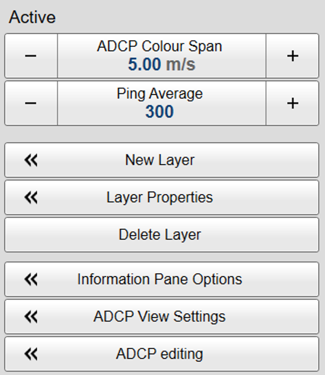
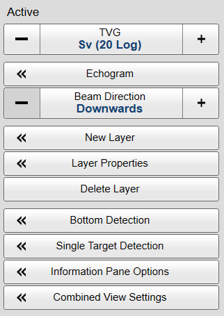
| Active menu for ADCP mode. | Active menu for echo sounder mode (ES mode). |
 |
 |
How to open
Select the Active icon.

The icon is located under the Main menu. Select the icon one more time to close the menu.
Description
Only brief descriptions are provided.
For detailed information about each function, page or dialog box, refer to the Functions and dialog boxes chapter in this publication.
Tip

If you do not need to use the menu system, you can hide it. This allows more space for the echo presentation.
Use Menu on the top bar to hide or show the menu. When the menu system is hidden, it appears temporarily on the left or right hand side of the screen if you move the cursor
to that position.
Functions and dialog boxes
| • | TVG (Time Variable Gain) TVG (Time Variable Gain) compensates for the loss of acoustic energy due to geometric spread and absorption. This makes the targets with the same strength appear with the same intensity independent of their physical distance from the
transducer.
|
| • | Echogram The Echogram dialog box allows you to set up the parameters controlling the echogram presentation. Two pages control the horizontal lines and the echogram type with applied TVG (time variable gain). One page controls how fast the echogram travels horizontally across the presentation.
|
| • | ADCP Colour Span The ADCP Colour Span function allows you to adapt the number of colours in the view to the range of the actual ADCP information. For instance, if the maximum vessel velocity data will be between +2 m/s and —2 m/s you can set this as your maximum colour
range. The velocity measurement (ADCP) view will then offer the best colour representation of the data with the best possible resolution. This function is available only when ADCP functionality is activated.
|
| • | Ping Average The acoustic Doppler current profiler (ADCP) works by transmitting constant frequency pings into the water. The velocity of the water current is calculated by measuring the time it takes for the echoes to be returned and the changes
in the frequency caused by the Doppler effect. Using only single pings for these calculations may result in velocity errors that are too large to meet the measurement requirements. For this reason, the average measurements from multiple pings are used. The average values are determined using a selected number of pings and the sliding average principle. Use the Ping Average function to specify how many pings you want to use.
This function is available only when ADCP functionality is activated.
|
| • | Beam Direction The purpose of the Beam Direction function is to turn the echogram presentation up-side down. This is typically used if the EK80 transducers are located on the seabed, or on the bottom of a fish cage, facing upwards.
|
| • | New Layer Different species often occupy different depth layers. Such layers may be defined by salinity or temperature, or simply by
ambient light or the availability of food. In order to study these species, the EK80 supports a Layer function. By means of this function, you can create your own depth layers in the water column to improve the dynamic data
required for analysis. The New Layer dialog box is used to create and insert a new depth layer.
|
| • | Layer Properties The Layer Properties dialog box is used to change the current properties of the chosen ("active") depth layer. If you only wish to change the range settings, you can also click and drag the line(s) in the echogram view.
|
| • | Delete Layer To delete a layer, select it in the echogram or in the Numerical information field (layer data shown with red text), and then click Delete Layer.
|
| • | Bottom Detection Locating the bottom (seafloor) is important for the EK80 system. The purpose of the Bottom Detection settings is to define the upper and lower depth limits most likely to be used during normal operation. You can also modify the setting for Bottom Backstep to change the bottom detection relative to the bottom echo.
|
| • | Single Target Detection The Single Target Detection parameters are used to control the operational settings for the detection of single targets. In order to detect single fish correctly, these parameters must be defined to suit the target characteristics. The chosen settings do not have any effect on the raw data you save during the survey.
The Single Target Detection parameters are available both as a dialog box and a page. The dialog box is opened from the Active menu. The page is opened in the Information Pane Options dialog box. The Single Target Detection dialog box is also used by the Calibration wizard.
|
| • | Information Pane OptionsThe EK80 system offers several information panes to provide additional and detailed data from the presentations. The information panes are opened and closed from the top bar. Several of the information panes are fitted with a Setup button. Select Active to open the Information Pane Options dialog box. Use the Information Pane Options dialog box to change the operating parameters for the data provided in the information panes.
The following pages are provided:
|
| • | Combined View Settings The Sv(f) information pane shows you the volume backscatter as a function of the frequency. The information is provided as a plot that shows the how the echo strength for a group of targets (for example a school of
fish) change with the operational frequency. In order to collect information from more than one channel in the Sv(f) information pane, you can use the Combined View Settings functionality to "combine" echo data from several channels.
|
| • | ADCP View Settings Use the ADCP View Settings dialog box to select the ADCP views you want to see. You can also define the parameters for these views. This includes horizontal axis units, labels, lines and ticks. These features are implemented to enhance the ADCP data presentation.
This page is available only when ADCP functionality is activated.
|
| • | ADCP Editing The ADCP Editing dialog box offers filters to improve the velocity measurements. You can enable and disable these filters individually. The ADCP Editing dialog box enables you to refine the ADCP data by setting quality parameters, remove unwanted backscatter and defining timestamp
source.
This page is available only when ADCP functionality is activated.
|
Context sensitivity
This is a highly adaptive menu. The choices in the this menu depends on which view in the display presentation that is currently "active". The menu may therefore change from one view to another. The name of the currently active view is identified at the top of the menu. The screen capture may not show you all the menu choices.
Note
Before you can change the settings related to a view, you must click inside the view to activate it. The changes you make are by default only valid for the active view. Several of the functions offer Apply to All. If you select Apply to All your setting is applied to all the views simultaneously.